简体中文
简体中文 English
1. Power transformation part (Test equipment: YNZZ series DC resistance tester)
| Cycle | Claim | Description |
| 1) 1-3 years or self-determined 2) After the non-excitation voltage regulating transformer changes the tap position 3) After the on-load tap changer of the tap changer is overhauled (on all tap sides) 4) After overhaul 5) When necessary | 1) For transformers above 1.6MVA, the difference between the winding resistances of each phase should not be greater than 2% of the average value of the three-phase. For windings without a neutral point, the difference between the wires should not be greater than 1% of the average value of the three-phase. 2) For transformers of 1.6MVA and below, the phase-to-phase difference is generally not more than 4% of the three-phase average value, and the line-to-line difference is generally not more than 2% of the three-phase average value. 3) Compared with the previous measured value of the same part, the change should not be greater than 2% 4) Reference implementation of reactor | 1) If the difference between the resistance phases exceeds the regulations when leaving the factory, the manufacturer has explained the reason for this deviation, and it shall be implemented in accordance with the requirements of 3) 2) The resistance value at different temperatures is converted by the following formula
|
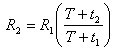 In the formula, R1 and R2 are the resistance values at temperature t1 and t2 respectively; T is the constant used for calculation, the copper wire is 235, the aluminum wire is 225
2. Winding insulation resistance, absorption ratio or polarization index (test equipment:YN-5000 Insulation Resistance Tester)
| Cycle | Claim | Description |
1) 1-3 years or self-determined | 1) When the insulation resistance is converted to the same temperature, there should be no significant change compared with the previous test result | 1) Use 2500V or 5000V megohmmeter
|
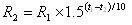 Where R1 and R2 are the insulation resistance values at temperatures t1 and t2, respectively
3. The tgδ and capacitance value of capacitive bushing (test equipment:YNJS-H anti-interference precision dielectric loss tester)
| Cycle | Claim | Description | |
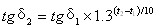
| 1) 1-3 years or self-determined 2) After overhaul 3) When necessary | 1) tgδ at 20℃ is not greater than the following values: 330~550kV 0.6% 66~220kV 0.8% 35kV and below 1.5%< 2) There should be no significant change between the tgδ value and the value over the years (generally no more than 30%) 3) The test voltage is as follows: | 1) Non-test windings should be grounded or shielded 2) The required value of tgδ for each winding of the same transformer is the same 3) The measurement temperature is based on the top oil temperature, try to make every time The measured temperature is similar 4) Try to measure when the oil temperature is lower than 50℃, The tgδ value at different temperatures can generally be converted by the following formula
| |
| Winding voltage 10kV and above | 10kV | ||
| Winding voltage 10kV and below> | Un | ||
| 4) When using the M-type tester, the test voltage is self-defined | |||
5. Insulation resistance of iron core (with external grounding wire) (test equipment:YN-5000 Insulation Resistance Tester)
| Cycle | Claim | Description |
| 1) 1-3 years or self-determined 2) After overhaul 3) When necessary | 1) No significant difference compared with previous test results 2) The core ground current during operation is generally not more than 0.1A | 1) Use 2500V megohmmeter (for long-running transformers Available 1000V megohmmeter) 2) When the clamp is led to the ground, the clamp can be measured separately |
6. AC withstand voltage test (test equipment:YNYDJ series power frequency withstand voltage test device )
| Cycle | Claim | Description |
| 1) 1~6 years (10kV and below) 2) After overhaul (66kV and below) 3) After replacing the winding 4) When necessary | 1) The test voltage value of the oil-immersed transformer (reactor) is operated according to the overhaul project (regular test is replaced by part of the winding Voltage value) 2) When all the windings of the dry-type test transformer are replaced, press out Factory test voltage value; for partial replacement of windings and regular tests, it is 0.85 times the factory test voltage value | 1) Frequency doubling induction or operating wave induction method can be used 2) For fully insulated transformers of 66kV and below, when the site conditions are not available, only the external rotation power frequency withstand voltage test can be carried out 3) The reactor is subjected to external construction frequency withstand voltage test |
7. the voltage ratio of the winding tap (test equipment: YNBC-H automatic ratio tester)
| Cycle | Claim |
| Cycle Claim 1) After disassembly and assembly of the tap switch lead 2) After replacing the winding 3) When necessary | 1) Compared with the nameplate value, the voltage ratio of each corresponding connector should not be significantly different and conform to the law 2) For voltages below 35kV, the allowable deviation of the voltage ratio of the transformer with a voltage ratio of less than 3 is ±1%; all other transformers: the allowable deviation of the rated tap voltage ratio is ±0.5%, and the voltage ratio of other taps should be within the impedance voltage value of the transformer ( %) within 1/10, but not more than ±1% |
8. No-load current and no-load loss (test equipment:YNRL-H Intelligent Transformer Capacity Loss Tester )
| Cycle | Claim | Description |
| 1) After replacing the winding 2) When necessary | Compared with the previous test value, there is no obvious change | The test power supply can be three-phase or single-phase; the test voltage can be rated value or lower voltage value (if the manufacturer provides the measured value under lower current, it can be compared under the same current) |
The above selection is for reference only. If you have any questions, please call: 027-81314188, 18627106286. For more information about Yuenenggao products, please click on the product center.
 Enter the mobile station